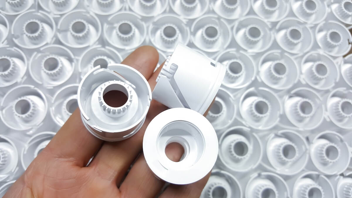
Every injection molding operation hits problems. Even on a validated, scientifically developed process running on a well-built tool, defects appear like short shots one shift, flash the next, sink marks that show up only when ambient humidity climbs. The difference between a high-performing molder and an average one is not whether defects occur. It is how quickly and methodically they get diagnosed and resolved.
That difference shows up directly on the bottom line. Most plastic processors lose several percentage points of total revenue to scrap and rework each year, and a meaningful share of that loss traces back to defects that a more disciplined troubleshooting process would have caught and corrected in hours instead of days. Short shots and flash are some of the top reasons injection-molded parts get scrapped, and both are usually solvable with process adjustments, not tooling changes, when diagnosed correctly.
This article walks through the most common defects in commercial injection molding, the causes behind them, and the troubleshooting steps that resolve them. Just as important, it covers the systematic framework that separates effective troubleshooting from trial-and-error parameter chasing.
Why a Systematic Approach Beats Trial and Error
The instinct when a defect appears is to start adjusting the press. Bump the melt temperature. Slow the injection speed. Add a little pack pressure. Sometimes it works. Often it does not, and now you have a defect plus an undocumented process change you have to back out of before the next root cause analysis.
Disciplined troubleshooting follows a different sequence. Before any parameter is adjusted, the defect is documented (photo, location on the part, frequency, shift conditions), the process data is reviewed against the validated setpoints, the material lot and dryer status are verified, and the mold is visually inspected. Only then are changes considered, one variable at a time, with measured outcomes captured and compared against the previous baseline.
This matters for two reasons. First, most defects have multiple potential root causes, and stacking parameter changes makes it impossible to know which adjustment actually worked. Second, a defect almost always traces back to a change somewhere in the system, a new material lot, a worn gate, a clogged vent, a cooling line that has lost flow. Find the change, and you usually find the cause.
Categorize the Root Cause Before Adjusting Anything
The fastest way to narrow a troubleshooting problem is to categorize the likely source of the defect into one of four buckets:
- Process. Melt temperature, injection speed and pressure, hold time, cooling time, back pressure, screw RPM. These are the variables you can change in minutes from the controller.
- Material. Resin lot variation, moisture content, regrind percentage, contamination, colorant inconsistency. These are the variables that often cause defects to appear suddenly on a previously stable process.
- Mold. Vent condition, gate wear, cooling channel flow, ejector wear, surface finish degradation. These typically cause progressive issues that get worse over time.
- Design. Wall thickness variation, sharp corners, gate location, ribs and bosses, draft angles. Design-rooted defects are present from the first part and require tool modification to fully resolve.
A useful rule is if a defect appeared suddenly on a previously stable process, look at material and process first. If it has been there since the first shot, look at design and mold. KS Plastic’s comprehensive guide to plastic injection molding covers the underlying mechanics of each of these categories in depth, which is essential context for accurate root-cause analysis.
Most Common Defects
With that framework in mind, here are the most common defects you will encounter on a commercial line, and how to work through them.
Short Shots
A short shot is exactly what it sounds like. The mold cavity does not fill completely, leaving a part with missing features, incomplete walls, or unfilled thin sections. Short shots are usually obvious on visual inspection and are one of the most frequently scrapped defect types in production.
Likely causes:
- Insufficient injection pressure or velocity to fill the cavity before the gate freezes
- Shot size set too low for the part volume
- Melt temperature too low, raising viscosity and slowing flow
- Cold mold preventing material from reaching distant features
- Vent blockage trapping air and resisting flow
- Worn check ring on the screw causing pressure loss during injection
- Long flow paths or thin walls beyond what the resin can fill
Troubleshooting steps:
Start with the simplest checks. Confirm shot size is set correctly and that cushion is present at the end of fill. No cushion suggests the screw is bottoming out before the cavity is full. Check melt and mold temperatures against the validated process sheet. Inspect vents for clogging.
If those check out, raise injection velocity in small increments. Faster fill keeps the melt front hotter and helps it reach distant features before freezing. If velocity is already at maximum and the part still does not fill, the issue is likely upstream: worn check ring losing pressure, undersized machine, or a design issue with flow length to wall thickness ratio. The latter usually requires a DFM review and possibly a tool modification, since you cannot process your way out of a flow path that is fundamentally too long for the wall section.
Flash
Flash is the opposite problem: material escaping the cavity at the parting line, around ejector pins, or through worn shut-offs, leaving thin protrusions of plastic on the finished part. Flash usually requires secondary trimming at minimum, and severe flash means scrap.
Likely causes:
- Clamp tonnage insufficient for the projected area at the running pressures
- Worn or damaged parting line allowing material to escape
- Excessive injection pressure or pack pressure forcing material past shut-offs
- Melt temperature too high, lowering viscosity and pushing material into mold gaps
- Foreign material on the parting surface preventing full closure
- Mold deflection under pressure (often a sign of inadequate clamping or a structural issue with the tool)
Troubleshooting steps:
First, clean the parting surface. A small piece of flash, debris, or splash from a previous shot can hold the mold open just enough to flash the next shot. After cleaning, inspect the parting line for wear, dings, or rounding, common at the corners of shut-off areas where pressure concentrates.
If the parting surface is clean and intact, reduce pack and hold pressure incrementally to find the point at which flash disappears without introducing sink. If flash persists at minimum pack pressure, the issue is likely clamp tonnage or melt viscosity. Lower the melt temperature in small steps, or move the program to a higher-tonnage press. Persistent flash on a properly maintained tool at correct pressures typically points to mold parting line wear that needs welding and resurfacing.
Sink Marks and Voids
Sink marks are surface depressions in thicker sections of a part, caused by the outer skin solidifying before the interior, then pulling inward as the core cools and shrinks. Voids are the same root phenomenon, but the skin holds and the shrinkage creates an internal vacuum pocket instead of a visible surface depression.
Likely causes:
- Wall thickness variation, particularly thick ribs or bosses adjacent to thinner walls
- Insufficient pack pressure or pack time to compensate for shrinkage
- Mold temperature too high, slowing skin formation
- Gate sealing before the cavity is fully packed
- Melt temperature too high, increasing total volumetric shrinkage
Troubleshooting steps:
Sink and voids are textbook process-and-design issues. On the process side, increase pack pressure and pack time first, as both push more material into the cavity to compensate for shrinkage. Verify the gate has not sealed prematurely by running a gate seal study; if it has, more pack pressure will not help and you need to either move the gate, enlarge it, or look at cooling.
On the design side, sink marks in ribs are almost always a wall-thickness ratio problem. The widely accepted guideline is that rib thickness should be no more than 60 percent of the adjacent wall thickness. KS Plastic’s essential design guidelines for injection molding cover these proportions in detail. When ribs are too thick, no amount of process tuning will fully eliminate sink, as the geometry guarantees uneven cooling.
Warping
Warping is dimensional distortion of the part after ejection, caused by uneven shrinkage as the part cools. A flat panel that comes out bowed, a box with inward-curving walls, a long part that twists: these are all warpage symptoms.
Likely causes:
- Non-uniform wall thickness causing differential shrinkage rates
- Uneven mold cooling between core and cavity sides
- Ejection while the part is still too hot to hold its shape
- Excessive packing creating internal stress
- Fiber-filled materials with anisotropic shrinkage (parallel to flow vs. across flow)
- Cooling channels poorly distributed, leaving hot zones
Troubleshooting steps:
The first move is mold temperature uniformity. Verify that the cooling channels on both halves of the tool are flowing freely and that water-out temperatures are within a few degrees of water-in. A mold with one side significantly hotter than the other will warp every part it produces.
Next, check the cooling time. Pulling parts before they reach a stable temperature lets them deform during ejection and on the conveyor. Adding a few seconds of cooling often eliminates marginal warpage at minimal cost to cycle time, and our blog on improving injection molding production efficiency covers how to balance cooling time against cycle time without giving up part quality.
If process adjustments do not fully resolve the warpage, the root cause is likely design or tool: non-uniform walls, poorly placed cooling channels, or an inappropriate gate location creating asymmetric flow. These require mold flow analysis and potentially tooling modification to address.
Weld Lines and Knit Lines
Weld lines (sometimes called knit lines) form where two flow fronts meet inside the cavity, typically downstream of holes, bosses, or other features that split the melt stream. They appear as visible lines on the part surface and, more importantly, create localized weakness because the two flow fronts do not fully fuse.
Likely causes:
- Melt temperature too low at the meeting point, preventing full fusion
- Injection speed too slow, allowing flow fronts to cool before meeting
- Inadequate venting at the weld line location, trapping air between the fronts
- Gate location creating unnecessarily long or unequal flow paths
- Material with high viscosity or rapid solidification
Troubleshooting steps:
Raise melt temperature first, in small increments. A hotter melt at the weld point fuses better. Increase injection velocity to reduce the time the flow front cools before meeting. Verify that vents at the weld line location are open, as trapped air at the meeting point produces both visible weld lines and burn marks.
If the weld line is in a structural area and these adjustments do not produce adequate strength, the durable fix is usually a gate change. Repositioning the gate to eliminate the flow split, or adding a second gate to control where the weld forms, is far more effective than process tweaking. Mold flow simulation should be used to validate any gate change before tool modification.
Burn Marks and Splay
Burn marks are dark or discolored areas on the part, usually at the end of fill, near vents, or in pockets where air gets trapped and compressed. The compressed air heats up rapidly (the diesel effect) and degrades the resin at the point of compression. Splay, by contrast, shows up as silvery streaks across the part surface, typically caused by moisture or volatiles in the melt.
Likely causes (burn marks):
- Trapped air with no vent path
- Injection velocity too high, generating excessive shear heat
- Melt temperature too high, causing material degradation
- Long residence time in the barrel, particularly on small shots in oversized barrels
Likely causes (splay):
- Wet material, most common cause by far
- Contamination of resin with incompatible materials
- Excessive screw RPM creating shear-induced gas
- Hot runner or nozzle temperature too high, causing localized degradation
Troubleshooting steps:
For burns, the first action is venting. Clean existing vents, and if the burn appears in a location with no vent, add one. Burns are the part telling you it needs an air escape. If venting is adequate, reduce injection velocity in the late stages of fill (a profiled injection speed often eliminates burns without sacrificing cycle time).
For splay, check material moisture first. Verify the dryer is operating at the correct temperature and dew point, and verify residence time in the dryer meets the resin manufacturer’s specification. A surprising portion of “process” splay issues are actually material handling issues, as wet pellets being fed into a hot barrel are a frequent culprit.
Flow Lines and Jetting
Flow lines appear as faint wavy patterns or rings on the part surface, typically near the gate or in thin sections. Jetting is more dramatic: a serpentine streak originating at the gate, caused by a high-velocity stream of melt shooting across the cavity before the cavity has built any back pressure.
Likely causes (flow lines):
- Melt or mold temperature too low, causing the flow front to cool prematurely
- Injection speed too slow, allowing the front to stutter
- Sharp wall thickness transitions disrupting flow
- Small gates creating localized cooling
Likely causes (jetting):
- Gate too small or oriented to project melt directly into the cavity
- Injection speed too high at the start of fill
- Melt temperature too low, raising viscosity and exaggerating the jet
Troubleshooting steps:
For flow lines, raise mold and melt temperature, then increase injection velocity to push the front through cooler zones before it hesitates. For jetting, the textbook fix is profiled injection: start fill slowly until the melt impinges and spreads, then ramp velocity up. If profiling does not solve it, the gate may need to be repositioned or resized to direct flow against a wall rather than into open space.
When Process Adjustments Are Not Enough in Injection Molding
A pattern emerges across most of these defects. Process adjustments resolve the majority of issues, but persistent defects on a properly maintained press typically indicate something deeper: worn tooling, an inadequate cooling layout, a gate in the wrong location, or a part design that violates fundamental injection molding principles.
The discipline is knowing when to stop tuning and start investigating upstream. A short shot that returns every time the press is set up to validated parameters is not a process problem. Sink marks that appear in every part regardless of pack pressure are a wall thickness problem. Flash that returns within hours of mold cleaning is a parting line problem.
In these cases, the right move is usually a structured DFM review combined with mold flow analysis, performed by an engineering team that can evaluate the design, the tool, and the process together.
Building a Common Troubleshooting Culture with KS Manufacturing
The molders who run the cleanest production are not the ones who never see defects. They are the ones who treat every defect as a piece of information, documented, root-caused, and fed back into the process and design knowledge base so it does not recur. Over time, that discipline compounds. Process windows widen. Scrap rates fall. Programs that used to require constant operator intervention run hands-off for entire shifts.
That cultural commitment, paired with scientific molding fundamentals and well-maintained tooling, is what separates molding operations that ship consistently from those that fight fires every day.
At KS Manufacturing, our plastic injection molding services are built on exactly this approach: scientific process development, ISO 9001-certified production, and an engineering team that treats troubleshooting as a structured discipline rather than a guessing game. Whether you are launching a new program, transferring an existing one in search of better stability, or working to resolve persistent quality issues on a current production run, our team can help. Contact us to discuss your project.